RelayPCB
Project description
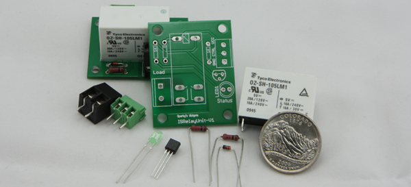
ISRelay is simply a basic breakout board for a mechanical relay. This board includes a reverse spike protection diode to contain the inductive spike which results when the magnetic field breakdowns in the coil of the relay. This design uses a small, simple and effective relay which is meant to act as an on/off replacement and to assist in automation. Suitable for low to medium loads we have tested it up to 1600watts HID lighting over >12hr lengths but feel that it should be kept at around 1000watt max.
Lets Get Started
how safely control mains with an arduino pin!
For this design we chose a small relay, since this unit is meant to fit into smaller places and can even be used to replace power switches on items which one wants to automate(a light fixture, ozone generator, fan or blind in the bedroom). Having reviewed the models out there we settled on the Tyco OZ-SH series and more specifically the OZ-SH-105LM1, this unit appears to carry its larger brothers contacts on a small draw 5-12v coil (112LM1 for the 12V) and has a max rating of 20amps @ 120v~ since we will only use this for medium loads of about 8amps this model should suite us just fine. One caveat is with inductive loads the contacts will tend to wear much more rapidly when the draw increases, something that should switch 300 thousand times may only switch 30 thousand.
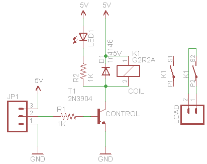
Now that we have our relay sorted we can build our design around it. The next component is a transistor, since we intend to interface directly with a µC and know that our relay uses a low draw coil we can chose a cheap small signal one like the2n3904. The transistor separates the higher draw coil from the Arduino pin which would be over saturated and may damage the Arduino should we try to connect them straight together.
Building from here, we need to add in a diode in a reverse manner, the reason for this is to block the voltage spike which develops when the relay’s coil breaks down during power down and will protect the outlying circuitry from any possible damage.(something like a fast diode such as a 1n4148 or even a rectifying diode like the 1n4007). The videos below show why this diode is important, the first showing an unprotected relay. The second a SW-03-010A(which contains a diode).
Now that most of the components are chosen lets see what our schematic looks like. Once we have the schematic down its only a matter of copying the relay unit multiple times if more then one is needed on a single board. Also adding in an opto isolator for extra protection could be a good addition. One could also add a darlington driver type device on a multi relay board to only use a few pins from the Arduino.

RelayPCB by Sparky’s Widgets is licensed under a Creative Commons Attribution-ShareAlike 3.0 Unported License.Based on a work at http://www.sparkyswidgets.com/portfolio-item/relaypcb/.