Smart Relay PowerStrip
Project description
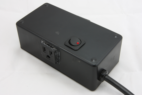
Smart Relay PowerStrip is an easy to build “Power Tail” which allows the control of 2 mains outlets via relays. These relays are controlled by an atmega328 (so it is Arduino compatible) which allows us to connect communications modules to allow remote control. In this tutorial we will use a Bluetooth module to create a rfcomm port on our linux server running SiriProxy. An xbee or even a tp703n would work great here too! All in all this is a pretty simple tutorial for anyone to complete!
Lets Get Started
So what do we need exactly
- Enclosure – keep everything safely packaged up
- DC power supply – this will convert the AC to DC for our smart relay unit to use
- SRCunit – The “Brains” of the operation
- Replacement power cord – our power cord
- Cable Reliefs – this will secure the power cord and make a professional finish
- Bluetooth module(can be Xbee,wifi, etc…) – wireless serial port!
- Snap In Outlets – our mains plugs!
- Heatshrink and crimp connectors – we’ll use these to put a nice finish on our connectors!
Basic Steps
Follow these in this order and everything will be just fine!
Well you made it this far, so that must mean you want to control something with SIri or by remote means! Lets jump right in and get started and keep you from waiting! Our Plan:
- Create DC power Supply – The first step (after acquiring all the parts) is to start building the DC power supply. You’ll need a transformer, 4 diodes and a capacitor, plus some perf board to complete this step.
- Prepare Enclosure – We need a few openings to allow the outlets and power cord(plus a power switch) to fit nicely into place, this is a good time to mount the power supply and SRCunit.
- Initial Wiring – In this step we will pre-wire the HV on the top half of the enclosure. This includes the outlets,switch, power cord. You can use about 12 inches of the power cord for the extra mains wire. You can also precut the lower HV wires now too.
- Final wiring – this step simple involves finalizing the HV wire runs and creating the connections (switched HOT to relays in and relay OUT to outlets)
- Final Step – Adding communications module and packaging the unit up!
Build unregulated DC power supply
I have since updated this build to use a nokia phone SMPS which works much better!
Grabbing our Diodes, Capacitor, and transformer lets build our unregulated power supply. There isn’t much to this unit, its simply a bridge rectifier and a transformer that feeds it with a cap to help keep things smooth on the output.
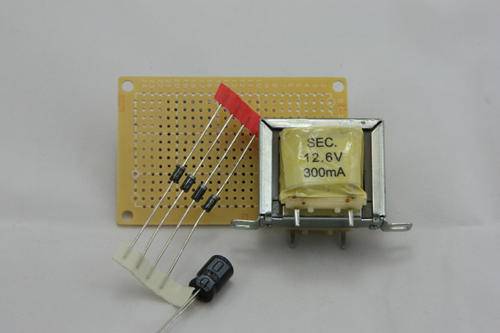
The First step is to arrange the diodes into a bridge configuration where the transformer can sit on top with the positive side of the rectifier sticking out.
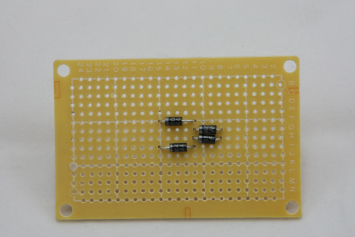
Then just use the diodes’ leads to make the rectifier’s connections on the underside.

Now mount the transformer and capacitor, the transformers primary will be at the edge of the perfboard and the secondary will straddle the rectifier at the junction of the diodes with the HOT on one part and the NEUTRAL on the other. the narrow diode junction then is the GND and the wide junction is our positive. We can simple wire the capacitor between positive and ground as shown in the photos.
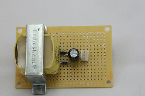
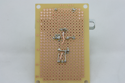
At this point the DC supply is ready to test, We got ~18V DC without a load and just under ~12v DC with a load of 3 relays (~300mA).
Prepare The Enclosure
This part isn't too difficult, just be sure everything has a snug fit and no shorts!
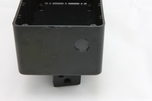
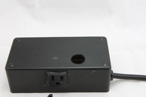
This step is pretty straight forward, we are going to make 4 holes in the top of the enclosure and mount the DC power Supply/SRCunit boards on the bottom of the enclosure. The Snap In outlets need 1” x 1” square holes, with the power switch requiring a 7/8”, and finally the power cord with a 9/16” hole. We use standard pcb mounting screws which work with 3/32” drill bits for mounting our pcbs directly to enclosures.
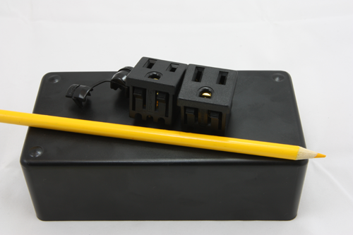
Lets start by cutting our square outlet holes, we used a dremel which doesn’t produce the best results but since the plugs will cover the holes and will be glued into place this shouldn’t matter.
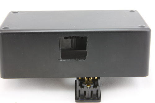
Then drill our 9/16 hole for the power cord/strain relief combo, it will be rather difficult to insert the strain relief and once it snaps into place we have a very stable power cable configuration.
Now we simply drill out hole for the power switch, you can always drill a smaller hole then enlarge it with a dremel, as with the outlet plugs the switch itself will provide a clean finish.

Initial HV wiring
Please take care when working with mains, I take no responsibility for peoples mistakes
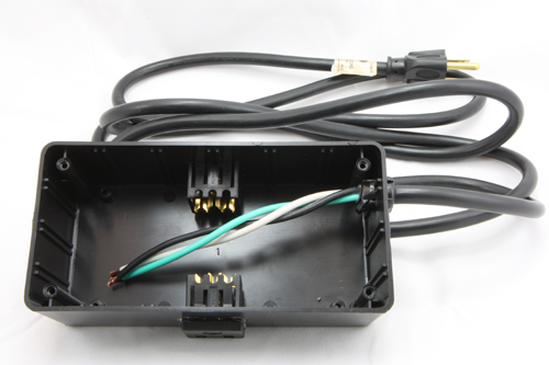
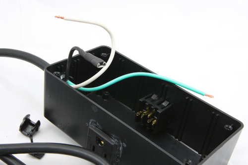
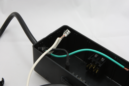
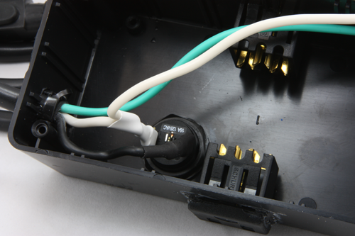
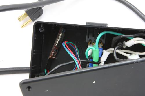
Once the enclosure is ready we can start to pre wire both the upper and lower HV parts. The first step is to ready the power switch, neutral bus and hot leads. now is a good time to pre cut our wire for connecting the relays, outlets, power switch and transformer. We’ll start by wiring the power cord into the switch. We’ll splice the neutral from the switch to transformer to outlets, while the hot will be cut at the switch, then spliced from switch out to transformer and then relay in.
Put a connector on the HOT, crimp then heatshrink it to finish the connection.
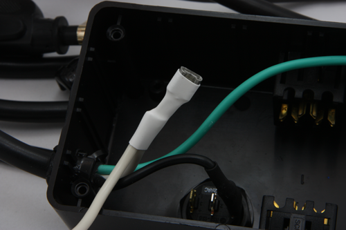
The next step is to take one of our pre cut feeder wires(neutral about 2.5″ long) and crimp this along with the power cord neutral. In order to make sure this connection wont work itself free add a small amount of solder to the joint(due to the connector and wires this will take a bit of heat but don’t over do it). After the connection is secure add a bit of heatshrink and finish it off nicely, just as with the hot line in.
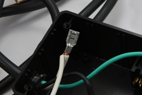
Then plug it into the switch and now the switch led will indicate when the power is on!
Final Wiring
This is just an extension of the last step, again please take care. safety first when working with mains
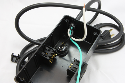
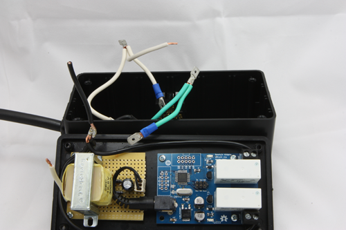
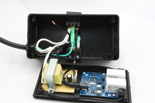
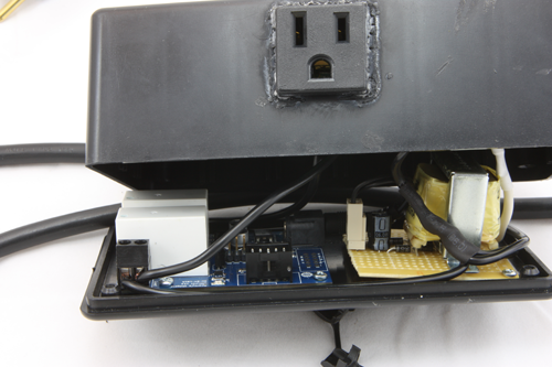
This step is an extension of the prior step and while straight forward is important to ensure safe operation of the unit as a whole. The first photo shows how the power supply and SRCunit are mounted and pre wired (sorry didn’t get good photos of that step but its tying the hot lines together then feeding into the relay ins). It also shows how the neutral and grounds will be tied together to allow both plugs to be grounded and have a neutral feed! The HOT of the outlets will be feed from the out of the relays.
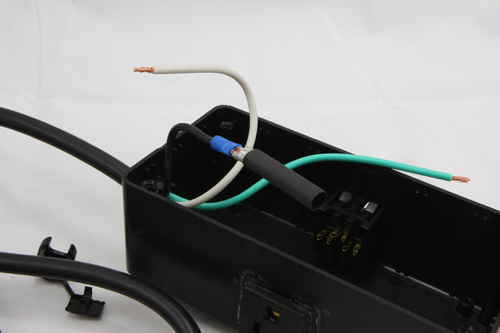
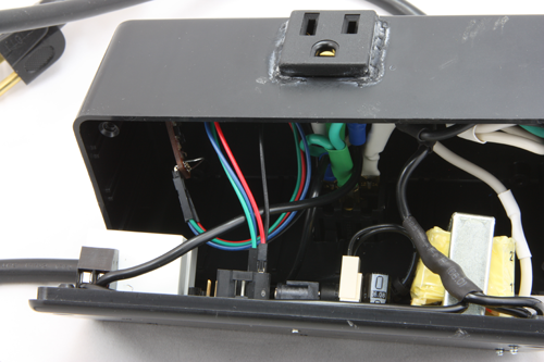
Now it is really a matter of connection the upper and lower HV sections together. The HOT will get a connector and will plug into the output of the power switch. while the neutral will tie into the neutral bus. You can also pre cut the HOT jumper to go from the relay out into the outlets. This is an important step to ensure proper heatshrink application, this way there will be adequate insulation.
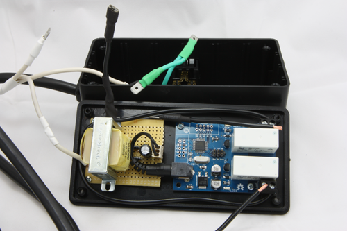
Then just plug everything together and finishing the relay outputs to the outlets plugs.
As with the other connection these should be made with crimp connectors finished with heatshrink, the relay ends are bare connections made with the screw terminals.
Final steps
This is an easy step, but care must be taken when packing everything up, we dont want this kind of magic smoke
This is pretty much the easiest part, just add in our communication module(Bluetooth in this case) making sure its tucked out of the way. and then its a matter of packaging the unit up and testing it out. Should it need programming you can open it and connect either to the ISP header, or the serial port!
Now test it out, there are a lot of applications for a unit like this! If you build one or a similar project let us know we’d love to feature it!

Smart Relay PowerStrip by Sparky’s Widgets is licensed under a Creative Commons Attribution-ShareAlike 3.0 Unported License. Based on a work at http://www.sparkyswidgets.com/portfolio-item/smart-relay-powerstrip/.