arduino ph probe interface
Project description
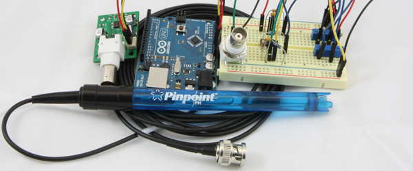
If you’ve ever wanted to make a pH meter out of an Arduino or RaspberryPi or to find the pH of a solution, needed to interface a pH probe or wanted to make your own pH sensor. This is an ideal project and tutorial for you. The idea of this project is to interface common inexpensive Marine/Lab/Horticulture pH probes with the Arduino style prototype boards that are very common these days. we will also learn about how to interface common chemical reactions and what Ion Selective Probes are such as the very common pH electrode. These types of probes have a very high impedance signal that poses a few design issues, thankfully we have modern ICs which take care of most of these concerns. Taking that and a few other considerations into account we can still produce a cost effective and accurate interface that even someone new to electronics can build themselves. Lets get started and interface a pH probe (electrode) with an Arduino or RaspberryPi!
Lets Get Started
So what is a pH electrode anyway
Let’s start by understanding what a pH probe does, once we know this we can build a circuit around those parameters. In the most basic sense a pH probe is a very simple single cell battery with a very high resistance, where the voltage produced is proportional to the hydrogen ion concentration around the probe and therefore proportional to the Log of the hydrogen ion concentration as expressed here: [latex]pH = -log10(ah)[/latex]. All this really means is when the concentration is greater on either side of the probe, the ion flow will induce a slight voltage between the probes electrodes, this voltage can swing both +/- which will indicate either an acid or base.
a pH probe’s construction consists of 2 electrodes, one in a solution of [latex]KCL[/latex] and the other in a low concentration of [latex]HCL[/latex]. The center “sensing” electrode (anode) is surrounded by a special glass bulb that allows (Na+, see below) ions to pass, the other electrode (cathode) is sealed off from the “sensing” electrode and is considered a reference. This is then connected by a porous ceramic plug (or quartz fiber) that forms a salt bridge with the test solution. This bridge is what forms a galvanic cell, and creates the simple single cell battery we can think of in a circuit. The potential between the electrode then tells us the concentration of the test solution and which side of the probe the concentration is on. For each pH step we see a ten fold concentration change, for example a pH of 8 has 1/10th the ion activity as a pH of 7.
its Sodium Ions I swear
Why tell us its H+ ions
Remember when I said the special glass bulb allows for Na+ ion movement, but I though pH measured Hydrogen ion activity like how acidic or alkaline something is? If pH probes are [latex]H+[/latex] ion selective probe, how does this work? Its actually really simple and important, the [latex]HCL[/latex] of the inner “sensing” bulb forms a hydrated gel that is [latex]Na+[/latex] sensitive so as the [latex]Na+[/latex] ions pass in and out of the test solution the Hydrated Gel responds with the creation of[latex]NaCl[/latex] splitting off [latex]H+[/latex] ions in the process! The activity is proportional to the [latex]Na+[/latex] activity! Of course the opposite is true and [latex]Na+[/latex] can be freed from their [latex]NaCl[/latex] bonds and cause the [latex]H+[/latex] to bond back with the free [latex]Cl[/latex] floating around. Now that is pretty cool I have to say. It also forms the basis of being able to make probes for a whole slew of ion types based only off a limited number of “porous” glasses available. Although the process isn’t perfect and the reactions wear down the Hydrated Gel and the salt bridge allows for contamination of the reference over time. This is why probes wear out!!
Anatomy of Probe and Amp
What are the basics of interfacing a probe
- Very low input Bias/offset high impedance op amp stage(or separate amp) for probe gain
- stable clean offset op amp stage for proper output voltages
- noise filtering and decoupling caps
- positive and Negative supply
- Optional: Gain control and Offset control
- Optional: Add µC for output digitization
The ideal pH Probe
This is what we base our calculations on, and measure probe against
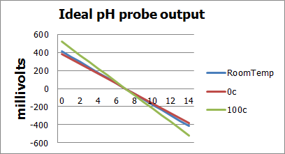
Lets look at a few of the characteristics of the ideal pH probe, as this is where we will get our basic inputs for our math. A key point to keep in mind are the Saturation ranges of the probe anything from pH 1 and under is considered Acidicly saturated meaning the concentrations are so high that we can’t really tell what it is. The same is true for the Alkaline ranges but this starts at about pH 12 and really saturates quickly blocking out 13 and above effectively.
- @pH 7 output of probe is 0 volts, @pH<7 voltage is positive, @pH>7 voltage is negative
- Total pH range is 0(strong acid) to 14(strong base)
- If probe generates -59mV/pH unit then our effective range would be +/- 7*59mV or +/-.414volts
- Depending on temperature the voltage generated per pH unit varies from -54mV@0c to -74mV@100c
Here are graphs showing the affects of temperature on probes and a degraded probe vs an ideal probe:
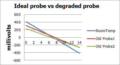
As the above graphs show, as probes age they tend to offset a tiny bit in either direction and also weaken their output potential. Luckily both of these can be compensated for either in software, or by adding gain and offset control in the circuit.
Basic Design
Lets get into the inner working and play a bit
In order to build an adequate amplifier there are a few considerations other then those pointed out by the ideal probe section. One consideration is the very high impedance that a pH probe has. Not only are the probes very high impedance they also are susceptible to noise, and the input stage is very vulnerable to drift/offset characteristics of the amplifiers used to interface the probe. There are a lot of Op-amps that can be chosen for the job, dont just look at the Input Impedance of the Op-Amp 🙂
A typical probe has an impedance of anywhere between 50MΩ and 500MΩ, and since 100MΩ*1nA=.1v even having a single stray nano amp can throw our measurement off by almost 2 entire ph units. The goal then is to choose an op amp that is adequate enough that will not load down the probe but that also has characteristics which will keep both the cost down and the accuracy up. When combined with the previous considerations about probe age and drift, a basic roadmap is made on how we can simply and effectively amplify and interface a pH probe signal.
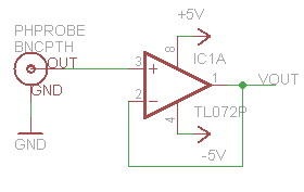
A very basic design we can utilize is a simple unity gain amp, a buffer circuit to separate the high impedance probe from our “low” impedance multimeter. We will build this design first for a couple reasons, the first being it is an effective way to compare our probes to the ideal probe model. the second reason being its really easy to build and can take only a few seconds, and demonstrates a base for how the offset(in an inverting config) will alter the signal. While I suppose you could use an LM358 for this I would recommend at very least the ST TL072 or a CA3140 this is to be sure not to load down the probe and get false readings. (As a note: The op-amp that I most often use is the TLC2262 other suitable amps are LMP7702, and the LMC6042 works a treat but is pricey, for really high end look at BB)
If we use the ideal probe numbers we should see an output of .414v at 0pH, 0v at 7pH and -.414 at 14pH. I had one aged probe read .150v at 4pH and -.04v at 7pH. .150-(-.04)=.190v/3(7pH-4pH)=63.3mV/pHunit which is our revised step number vs the ideal step of 59mV/pHunit. This gives us a useful baseline to compare our circuits while negating most of the error associated with different probes aging rates etc…
The diagram below describes the interaction of an amplifier with a fixed gain and offset building on from the very basic unity gain amp design.
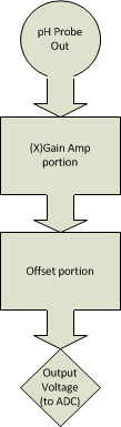
Voltage evolution through simple fixed Gain/Offset circuit (Using Ideal probe characteristics)
Assuming [latex]X = 4.7[/latex], and output range should be 0-5v
[latex]+/- .414[/latex] [latex]Vout =(1+X)*Vin[/latex] (simplified non inverting op-amp gain formula) [latex]5.7*.414 = 2.36[/latex] (*2= 4.72 total voltage swing) [latex]Vaout=~5v=Vin+Voffset[/latex] – Offset range acid side [latex]Vbout=0v=-Vin+Voffset[/latex] – Offset range base side [latex]5-2.36=2.64>Voffset>0-(-)2.36=2.36[/latex] Lets pick 2.5v for our offset in this example [latex]Voffset=2.5v[/latex] (/2 1.25v this will be our Vin for the offset circuit as we will see later)Thus making our effective output range
[latex]Vlow=Vbout+Voffset=-2.36+2.5=.14v[/latex] [latex]Vhigh=Vaout+Voffset=2.36+2.5=4.86v[/latex] [latex]pH0=.14v[/latex], [latex]pH14=4.86v[/latex]Basic Design: Gain and Offset
Lets add up what we have learned so far and create a circuit based on the math above!
Now that our ranges and requirements are better understood, we can start to build a circuit out of the simplified block diagram. Not only do we need 2 op amps(A dual package like ST’s TL072 will suffice for the simple/cheap circuit but dont have the best offset characteristics) one for the amp stage and one for the offset stage. We also need either a negative Vreg or charge pump/inverter (cl7660,TPS60400) since the amp stage is required to swing into the negatives.
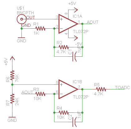
As shown above, there isn’t really much to this very basic circuit. If you are familiar with op amps you will see a standard non-inverting configuration hooked up to a differential amplifier(configured as an offset stage) the net result of this circuit will mimic what we designed in the block diagram. The capacitors are added for stability(and noise blocking at certain Fqs) and aren’t tuned in this schematic nor are the values of the resistors. The ratios are the important part([latex]G=1+(R2/R1)=5.7[/latex],[latex] G2=1+(R4/R3)=2[/latex]) as we can see from the schematic and prior math, the offset voltage is doubled which is why we halved it earlier.
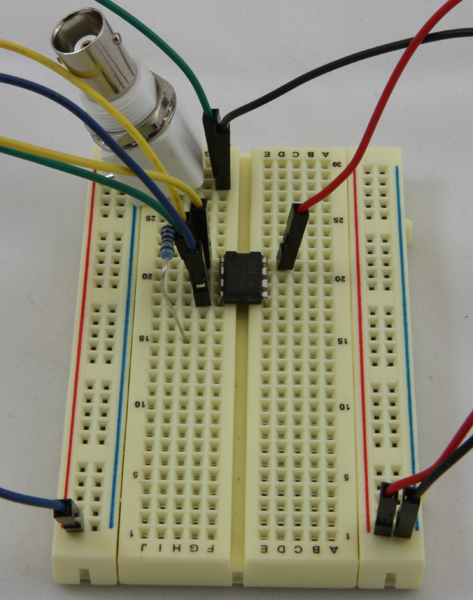
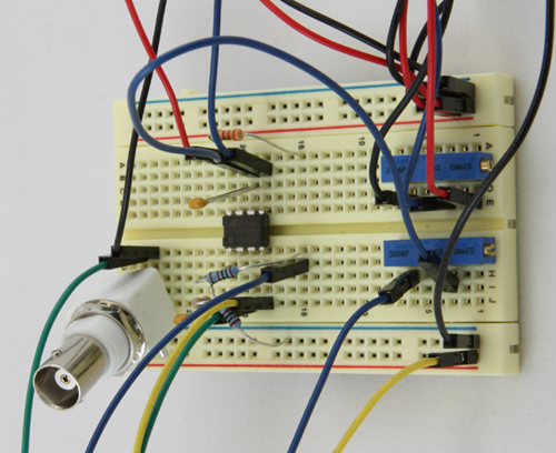
With our basic schematic ready lets build a breadboard version and takes some samples from a few probes(old and new) and see how the results stack up to what we should expect to see from the Ideal Probe Model. We will account for the ph calibration in software, calibrating with pH7 and pH4 reference solutions. Once we have our calibration numbers we can map new readings based on the reference readings to calculated unknown pH.
The only thing needed to wire up at this point is the offset voltage, positive and negative rails. Once we feed in our input from the pH probe we can read the voltage out from the end of the 3.3k Resistor at top col 15.(Note trimmer shown is set to proper offset, and is assumed fixed, but well be using this in the adjustable circuit so I just left it on there)
With a bit of quick programming in the Arduino environment, we can perform a calibration step to allow us to use the map function. This is a quick and dirty method of getting our ADC reading into a useful range based on the max/min calibration reading(reading at pH4 and at pH7). after running the calibration a dip in my tap water shows it at about 7.3 pH (map(analogRead(A0),pH4cal,pH7cal,400,700)) my pH pen shows it to be about 7.2, putting us in a reasonable shooting distance which isn’t bad for such a cheap un tuned circuit.
Some improvements with filtering caps and possibly a slightly higher gain to account for aged probes can be made at very little cost and effort. Also tuning the resistor values will help quit a bit in both power consumption and over signal quality. Recommended values R1-47K,R2-200K,R3-200K,R4-200K, R5-3.3-4.7K, C1-.47uF,C2-.47uF(additional caps can be place at probe input to ground, and final output to ground these can be 100pF to .1uF depending on noise characteristics)
Basic Design: Adjustable design
Some prefer to calibrate within the hardware, lets look at how to provide a slope and gain adjustment
The previous section showed the simplest form of a pH probe amplifier/ADC interface circuit. While being very cheap and quite effective it does have a couple drawbacks. First and really the most noticeable is the lack of adjustment for probe condition. We will call this calibration and normalization, and these 2 steps will help the circuit be more flexible when it comes to probe condition and usable range.
Another improvement that can be made is adding in a “buffer” configured op amp stage to separate the high impedance end from the low impedance end, and we could also choose a “better” op amp for the initial stage. We will explore all these options and see which one gives us the best bang for buck.
In order to normalize(Zero for 7pH) we will need to add an adjustable offset control to our simple circuit. Since the pH probe should produce 0v at pH7 the gain portion of the circuit will not affect this reading, which is why we adjust it in the offset portion. When combined with gain adjustments we can make a simple circuit that is able to be calibrated much like most commercial pH units.
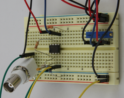
In the most basic sense the gain controls our slope(think the above graphs) and the offset zeros it around 7. Below is the same simple schematic as above only this incorporates the trimmer pots that will let us adjust for calibration and normalization. A couple more filter caps were added(as suggested in the previous section) as well.
For simplicity I set the trimmers for gain of 3 and followed our block diagram for the recommended offset voltage(1.25v into pin5). The output of the amp when place into pH4 calibration solution was 2.09v and 2.66v in pH7 solution. To find out if this matches what we should be expecting lets do a bit of math, First lets find the range of the difference between the 4 and 7 calibration readings. [latex]2.66-2.09=.570mV[/latex], by dividing this by our gain [latex]570/3=190mV[/latex] we get our voltage swing between the two solutions.
From the ideal pH probe scenario we know that a pH probe should produce about 59mV per pH unit, by dividing our observed range by this step number we can see if our amp is working correctly. [latex]190/59=3.22[/latex] which indicates a difference of 3.22pH units from Neutral(7pH) [latex]7-3.22=3.78pH[/latex] or about 5% off our pH4 solution when using the ideal model. When we use our math from the unity gain example(63mV/step) our accuracy is just under 1%, [latex]190/63=3.01 7-3.01=3.99pH[/latex]. Once we can check what condition our probe is in, even with a cheaper Op-Amp on breadboard, we can achieve very good results for little investment.
Considering the breadboard version has no noise/stabilization capacitors and the probes are quite aged, on an un calibrated circuit this isn’t too bad really. With a bit of calibration or math we can adjust for these slight differences. Add in some properly tuned filter caps and resistor values and you could have one nice pH probe interface(especially when paired with an opa129 or something like the LMC6001 and a unity gain buffer between that and the µC).

pH Probe interface tutorial by Sparky’s Widgets is licensed under a Creative Commons Attribution-ShareAlike 3.0 Unported License. Based on a work at http://www.sparkyswidgets.com/portfolio-item/ph-probe-interface/.