DIY pH Meter
Project description
For Maker Faire 2013 I wanted to demonstrate the use of some of my widgets in a very simple way. One of the best ways I thought would be to create handheld pH meter similar to what is commercially available using my LeoPhi boards. I decided to take a few parts I had laying around and create a standalone handheld meter with a rechargeable battery. I don’t think there is anything on the market like this, and I got a metric boatload of questions about these and how to make them, so with out any more delay. How to make a DIY handheld pH Meter!
I just wanted to add a couple updates and post my source code for running the OLED version, after quite a few requests I though it would be a good idea to push it up to github. The unit is still working strong, LeoPhi in standard operation mode uses just shy of 30mA and with the unit on constantly it can last for over 12 hours. I added a simple battery gauge and some other other improvements to make usage better. Overall this is a good project and something I think I will refine more and turn into a kit. Full code breakdown at bottom.
[repo path=”SparkysWidgets/DIYpHMeterFW”]

What's Inside
Not too much that is the key, I use my LeoPhi board to drive everything!
These builds are really simple, at the heart of it all is a LeoPhi driving everything, I also decided to use a boost converter and LiPo battery from Sparkfun to power it all. While I could use the battery by itself, the Vref of the ADC would always be changing, and I cant do a cool trick and monitor the Battery voltage to estimate charge. By adding in a boost converter I got a 5V supply and Vref, that way I can tap into the battery V+ with an ADC pin 🙂 In the first build I went with a simple 4×20 Char LCD, it was basically just parts I had laying around. To round things out I added a power switch and one button for calibration as well.
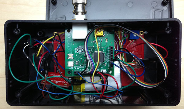
There really isn’t a whole a lot to this as you can see, sorry for the rats nest 🙂 Now to take a look at some of the parts in more detail!
LeoPhi

A close up of a LeoPhi Arduino pH sensor interface, the full main digital and analog ports are broken out and make creating DIY pH meters really easy!
At the heart of everything is a LeoPhi unit. I basically designed LeoPhi for this reason, to be able to build programmable meters with it. By breaking out the Key Arduino Digital and Analog “ports” hooking up LCDs and sensors to LeoPhi is extremely easy. Having 2 serial ports (Serial is USB, while Serial1 is on the headers) allows you to use the extra pins or have a wifi/xbee/BLE unit in there as well, but still able to charge and program via USB. A cool example because of the native CDC support via the Leonardo bootloader you can also hook LeoPhi right up through USB to a TP-703n router and still have access to the Serial1 port or pins, accessing LeoPhi via a RESTful interface at the same time! With some planning on the enclosure the RGB Led could be piped out for indication as well!
Battery Power
By using battery power we reduce the chances of ground loop errors and looping noise from other sensors!
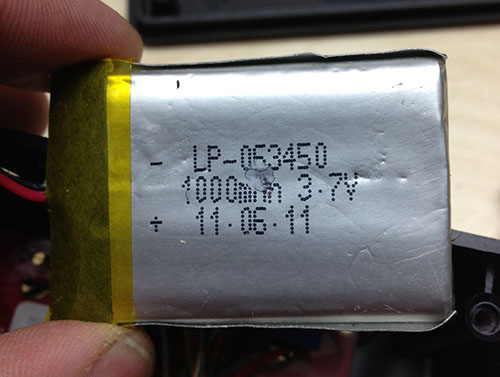
I want to have a 5V rail for my main power supply, since this is only a 3.7v LiPo I will need a boost converter. While I could technically use this to power LeoPhi directly the Vref of the analog in will slowly decrease as the battery draws down. Also if we use a boost converter we can read the battery V+ pin directly with an ADC pin and get a rough Idea of charge! I got the Boost converter and a few these batteries from my friends over at SparkFun!
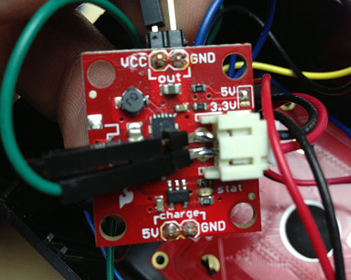
All I did was add in a standard male header onto the battery in connections. This gives me another ground and I can pull the battery voltage right from here. There is a caveat to this, as the ADC pin that we read the voltage from will also have the side effect of powering the device in some of my tests I found it could even power the display. Since I wanted to be able to switch from a charge to run state I decided to use a DPDT switch and switch the V+ pin to the ADC as well.
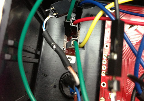
Although it is a bit of a rats nest, the switch simple changes the battery around from Charge to 5V out and vise versa, the other part disconnects the ADC when in charge mode, we don’t want the boost converter running while its charging, I think the batteries would be very unhappy! The button is connect to an input and we do some software debouncing, its a simple state machine and use the button to change states (Cal7, Cal4, Info dump, and Run).
Prepare enclosure
Not much here but a messy bunch of cuts sorry to those that kick ass at packaging projects
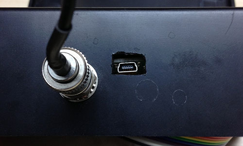
To finish it off I simply made some rough cutouts for the LCD and one for the USB port. I use an iPhone wall charger to charge the batteries, you can also log data through the USB port too! I will leave most of the screen and enclosure parts to peoples imaginations, I expect to see some awesome builds so please let me know if you have one!!
It sure is ugly, but it works and for a prototype I built in under an hour I would say not bad (hey I need to get a CNC so I can make better enclosures) especially using a utility knife. Other than some more bad case work all it needs is to be buttoned up and charged!
How does it work
Not bad actually I am impressed with how easy it is to calibrate and use
Wow, its actually pretty easy to use and works great, I thought it would be handy but I find myself using it everywhere I can. One side effect is the battery drains fairly fast with the large 20×4 char LCD. At this point I wanted to start using OLEDs so I picked up an awesome color OLED from 4D systems. (man that screen is really gorgeous, the picture just don’t do it justice!) but more on this later. The handheld pH meter prototype works good enough that I want to improve it.
Better Screen, smaller case
I thought one way to improve the over all build is to shrink the case
I decided to shrink the case and try and get the form factor smaller so that a 96X96 pixel OLED would look just about right on the face on an enclosure. While at JB Saunders I found a little case that was perfect and decided to use it for this part of the build. One side effect was that the standoff made it very difficult to fit a LeoPhiV2 so I dug out an older V1 version and put it to work.
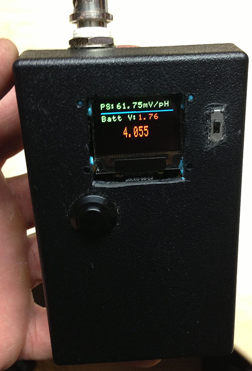
The case turned out to be the perfect size really, any smaller and it would have been somewhat difficult to fit everything in. The rats nest inside is much like the earlier build just more compact so I won’t bother showing all the other parts besides the case and screen are the same. Lets look at bit more at the OLED screen. This thing rocks, the colors are so nice and crisp its hard to show in photos just how great it looks. I decided to take advantage of this and add some color in when pH is out of range too much it’ll show the pH value in red (Same with battery voltage) and yellow when a little out of range. using the screen like this you can convey a ton of info in such a small space. I will have to work more with 4D systems screens especially the OLEDs ones! Overall the 2nd build is great, battery lasts a very long time and you can get lots of info just by quick glances, some improvements I would make are to add BLE module that way one could read from phones or log data etc… Also a streamlined version in a single board to fit a polycase enclosure would be awesome!
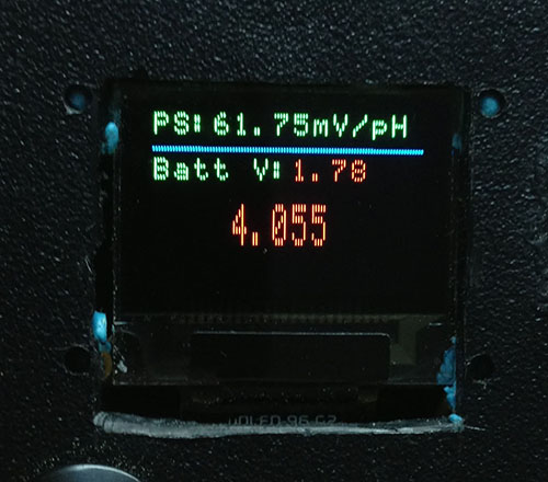
Its hard to tell But man those color OLEDs are sexy!!!!
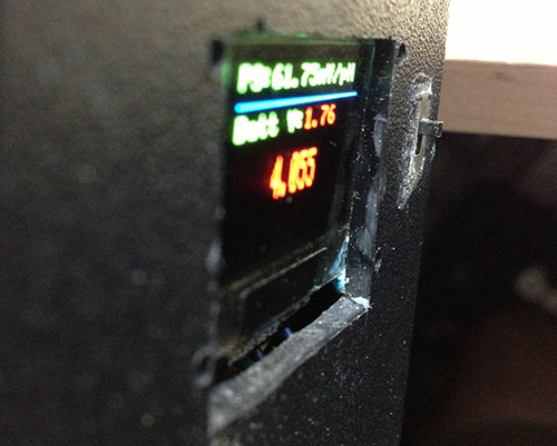
The OLEDs also have amazing viewing angles too, I highly recommend anyone who is going to build projects with screens to look into OLEDs. And for stuff like this you can’t beat the 4D systems ones that can work with arduino out of the box. I hope everyone finds this useful!
[git:sourcecode_cpp@https://github.com/SparkysWidgets/DIYpHMeterFW/blob/master/DIYpHMeterOLED.ino]